
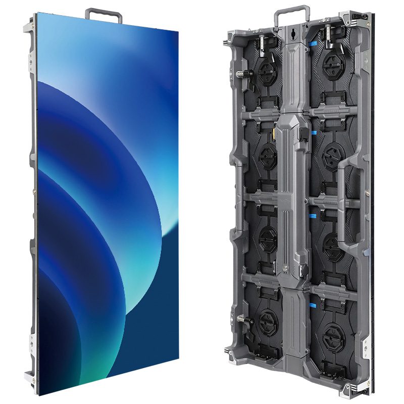
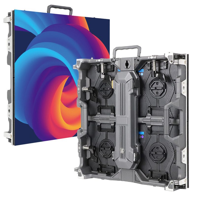
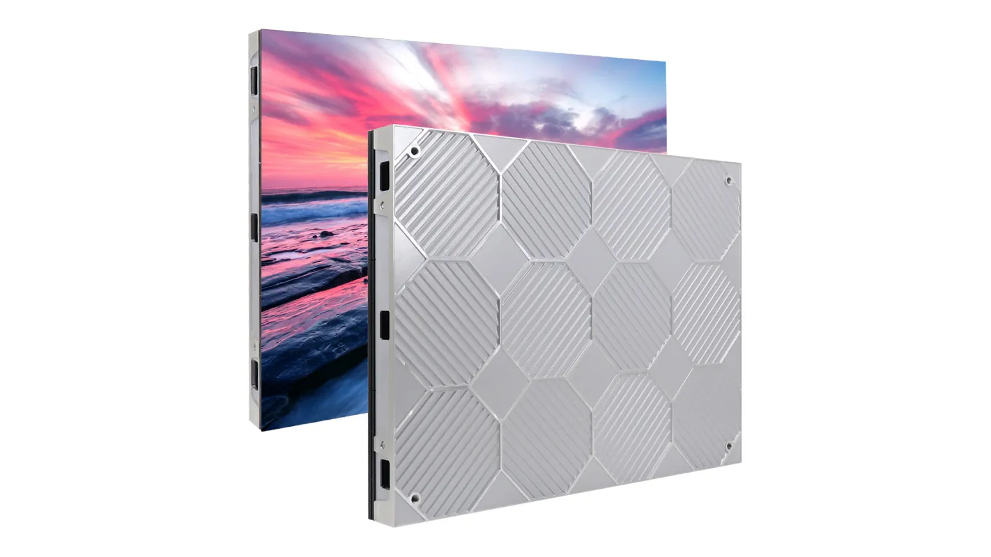
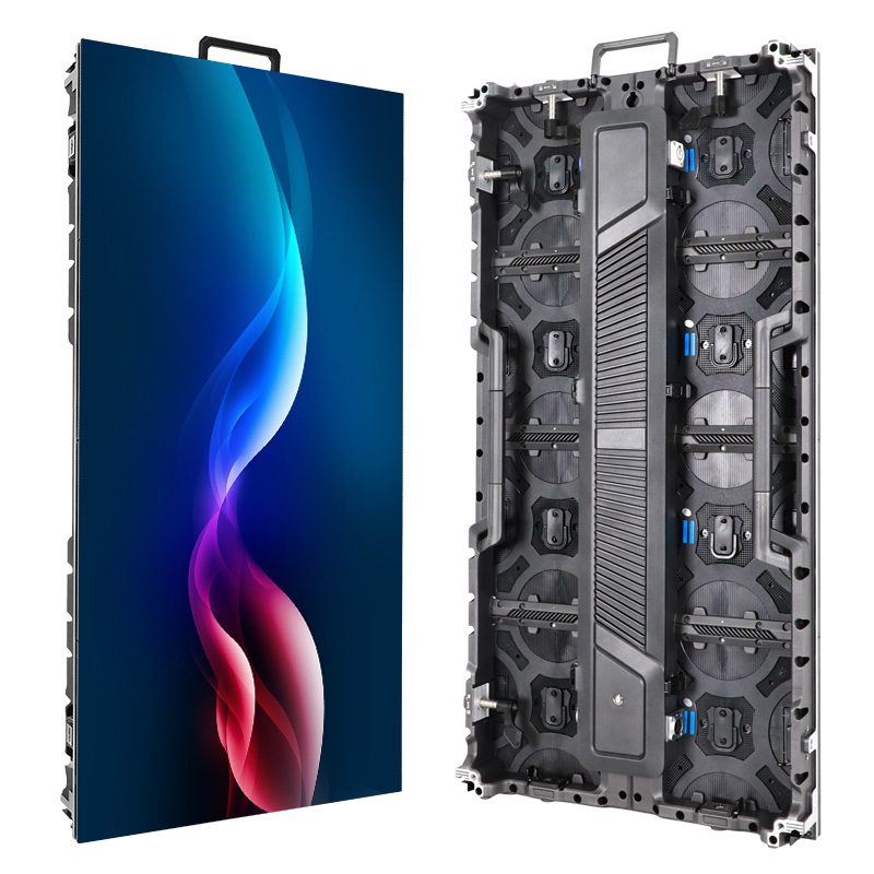
LED screen repair usually starts with isolating a fault, not replacing the entire display. A black cabinet, flickering module, missing color, or dead pixel can originate in the power supply, signal path, configuration, or LED module itself. Testing those areas in a controlled order helps avoid replacing working parts.
This guide covers direct-view, modular LED displays used for advertising, events, churches, retail, and control rooms. It does not describe LCD television backlight repair or laptop panel replacement. Here, an LED module is a replaceable pixel board; a cabinet holds modules, power supplies, and receiving electronics.
Use the symptom tables to choose your next check, then follow the relevant LED screen repair procedure. Operators can inspect source settings and record symptoms. Internal electrical measurements, soldering, water-damage assessment, and structural repairs belong to qualified technicians working to the equipment manufacturer’s service instructions. Stop immediately for smoke, burning smells, exposed conductors, or unstable mounting.
1. Is LED screen repair possible without replacing the display?
Yes. A modular LED wall can often be restored by replacing a cable, module, receiving card, or power supply, provided a compatible replacement is available. The repair decision depends on fault extent, parts availability, color matching, access costs, and the condition of the remaining system. One failed pixel board does not automatically justify replacing every cabinet.
Before planning LED screen repair, identify the cabinet model, module part number, pixel pitch, controller, receiving card, and installation date. Photograph the fault and component labels. Record whether the issue began after transport, rain, a power interruption, new content, or a configuration change. These details are more useful than describing the whole screen as broken.
| Condition | Likely approach | Check before approval |
|---|---|---|
| One damaged module; matching spare available | Replace the module, then test and calibrate | Electrical compatibility, batch, mounting, color uniformity |
| Cable or connector fault | Replace the confirmed defective connection | Connector rating, pinout, strain relief, upstream damage |
| Isolated PSU or receiving-card failure | Replace the approved component | Supply specifications, configuration backup, firmware compatibility |
| Repeated faults across aging cabinets | Compare staged refurbishment with replacement | Total labor, downtime, spare availability, remaining performance |
| Widespread corrosion or structural damage | Obtain a specialist assessment before reuse | Electrical integrity, frame safety, weather sealing, repair feasibility |
Ask for an itemized LED screen repair quotation covering diagnosis, parts, access equipment, transport, calibration, testing, and warranty terms. There is no reliable universal price or savings percentage: replacing a small indoor module and servicing a high outdoor billboard involve very different costs. Compare the full installed cost and expected service outcome, rather than the component price alone.
2. Common LED display faults, causes, and repair methods
Start LED display troubleshooting by locating the boundary between normal and abnormal areas. Is the entire wall affected, one data chain, one cabinet, one module, or individual pixels? Follow the documented signal route, which may snake across the wall rather than run left to right. A fault upstream can interrupt several downstream cabinets.
| Symptom | Possible causes | Useful first test | What the result suggests |
|---|---|---|---|
| Entire screen black | Power, blanking, input loss, controller output | Check status indicators and a supported internal test pattern | A working pattern directs attention toward the input path |
| Several consecutive cabinets dark | Shared power branch or interrupted data chain | Locate the last working and first failed cabinet | The boundary narrows the connection or supply to inspect |
| One module dark | Module power, ribbon cable, HUB output, module fault | Controlled substitution with compatible known-good parts | A fault following the module supports a module diagnosis |
| Dead or stuck pixel | LED package, solder joint, driver channel | Compare red, green, blue, and black patterns | Color-specific behavior identifies the affected channel |
| Flicker or intermittent reset | Connection loss, supply instability, heat, configuration | Compare internal patterns with source video | Separates input-related behavior from downstream faults |
| Rows, columns, or color blocks | Ribbon/HUB connection, scan configuration, driver circuitry | Compare pattern geometry with module boundaries | Repeated geometry guides local circuit or configuration checks |
| New module has a different tint | Batch mismatch, calibration, incompatible hardware | Inspect low-gray and white patterns | Separates uniformity issues from missing color channels |
| Failure after warm-up or rain | Cooling fault, overloaded connection, moisture ingress | Record conditions and isolate unsafe equipment | Requires environmental and electrical inspection |
01. LED screen repair for a black screen or no signal
Check the source device, selected input, output enable, brightness, blackout function, and scheduled blanking before opening a cabinet. Confirm that the player is actually producing an image at a supported resolution and frame rate. A processor’s “No Signal” message describes its input state; the LED wall itself may remain black without displaying that message.
If the controller supports an internal test pattern, activate it through the documented menu. A stable pattern across the wall indicates that much of the downstream display path is functioning under that test condition. Investigate the source, input cable, adapters, and processor settings next. A failed pattern instead requires checks of output configuration, data distribution, cabinet power, and receiving cards.
For LED screen repair involving a partial blackout, label the last healthy cabinet and first dark cabinet along the actual data chain. A technician should inspect their connecting cable and the first dark cabinet’s power. Do not assume every downstream receiving card has failed. Indicator meanings vary by model, so a blinking LED is evidence to interpret using the manual, not a universal diagnosis.
02. Dead pixels, bright spots, and missing colors
Display red, green, blue, white, and black patterns at the manufacturer’s recommended test settings. Note which pixels fail on each color. A pixel dark only on red has a different fault signature from a whole row missing red. A pixel that stays bright on black may involve an LED package or driver fault and needs circuit-level diagnosis.
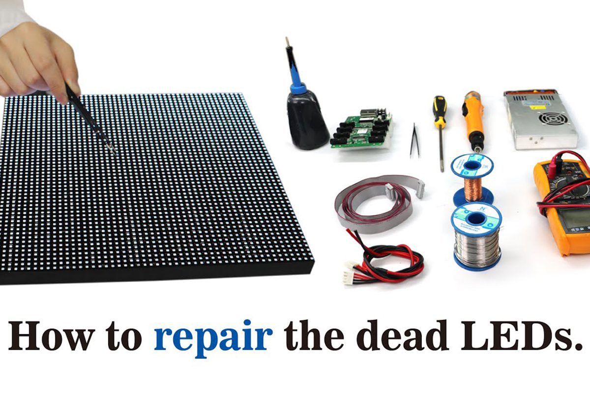
LED screen repair at individual-component level requires magnification, suitable rework equipment, matching LEDs, and an approved temperature process. Random heating can lift pads, damage neighboring packages, or alter the surface appearance. For field restoration, a compatible module swap is often more practical; the removed module can then undergo bench diagnosis. COB and encapsulated GOB products may require manufacturer-specific repair methods.
03. Ghosting, image distortion, and incorrect mapping
A duplicated edge, scrambled cabinet, or repeated image does not automatically mean a defective LED. Compare a stationary grid pattern with normal video. If the grid is misplaced, check cabinet mapping, module dimensions, data-group assignment, and scan configuration against the commissioning backup. If only moving video looks wrong, examine scaling, input timing, and processing settings.
Keep three concepts separate during LED screen repair: video frame rate, LED refresh behavior, and camera shutter timing. They interact but are not interchangeable specifications. Bands visible only through a camera can result from capture timing. Adjust the camera and supported processor settings before diagnosing hardware. Persistent artifacts visible directly on internal patterns need further display-side investigation.
04. Flickering screens, stripes, and intermittent faults
Observe whether flicker affects the whole wall or a repeatable local area, and whether it changes with content or warm-up. Test a known-good source path and then an internal pattern. Power down before reseating internal cables. Replace one suspect cable at a time with an approved equivalent, documenting whether the symptom disappears, moves, or remains.
A qualified technician can compare the specified low-voltage supply at the PSU output and module input under the same controlled load. A significant difference can indicate cable or connector loss. There is no universal voltage setting for all modules: use the nameplate and service documentation. Raising voltage to conceal a bad connection can damage electronics and does not correct its cause.
If LED screen repair resolves a connection problem but stripes remain, inspect the HUB board, ribbon orientation, receiving-card configuration, and module driver circuitry. Do not send an unfamiliar configuration to every cabinet as a trial. Preserve the known-good setup, confirm hardware compatibility, and test the affected area using the supplier’s procedure.

05. Overheating, moisture, and delayed video
For faults that appear after warm-up, record ambient conditions, cabinet temperature alarms, fan operation where fitted, and blocked airflow. Inspect filters, vents, connectors, and supply loading. A hot spot at one connector deserves investigation even if the average cabinet temperature seems acceptable. Cooling changes should follow the cabinet design; improvised openings can compromise weather protection.
After water ingress, isolate the affected circuit and arrange inspection before restoring power. A dry exterior does not establish that connectors, power supplies, or circuit boards are safe. LED screen repair must address the ingress path and corrosion as well as failed parts. Outdoor protection depends on correctly installed seals, cable entries, drainage, and covers.
Video latency is a separate diagnostic branch. Compare a direct supported source connection with the normal chain of converters, scalers, wireless links, and processors. Frame buffering and processing can add visible delay; shortening an ordinary cable is not a general latency cure. Check supported low-latency modes and their restrictions. External audio faults should be isolated in the audio system rather than attributed automatically to LED modules.
3. When do you need professional LED display repair?
Professional LED screen repair is appropriate when the work involves mains wiring, recurring breaker trips, burned connectors, water damage, component soldering, elevated access, or structural stability. Stop repeated power cycling when a protective device trips. A protection event is a reason to investigate the fault, not to install a larger fuse or bypass the circuit.
01. Prepare evidence for the repair team
Send a full-wall photograph, close-up of the fault, short video of intermittent behavior, and pictures of model labels. Include cabinet coordinates, controller and receiving-card models, recent changes, and tests already completed. Preserve error messages and configuration backups. For EagerLED technical support, identify the original order or project if available so the team can check the supplied hardware.
Do not describe a suspected cause as a confirmed failure. “Cabinets three through five went dark after transport” is useful evidence; “three receiving cards are broken” may send diagnosis in the wrong direction. A clear service record makes LED screen repair more efficient and helps the supplier select suitable replacement parts.
02. Protect configuration and warranty information
Ask the supplier which software version, firmware, configuration file, and repair method apply to the exact hardware. Save the working screen map and calibration data before a card replacement or authorized configuration change. Avoid firmware updates as an exploratory fix unless support identifies a relevant issue and supplies a recovery plan.
The NovaStar NovaLCT V5.6.1 manual documents calibration-coefficient management for replacement receiving cards and modules. These procedures depend on supported hardware and software. They illustrate why LED screen repair is not complete merely because a replacement board lights up: configuration, calibration, and saved operation also matter.
4. Practical LED screen repair skills and replacement checks
01. Isolate the fault with controlled substitution
Change one variable per test. With equipment safely isolated, a qualified technician can replace a suspect cable with a known-good equivalent and retest. If necessary, test a confirmed compatible module on a verified safe supply and signal path. Never connect a valuable spare to a location with unresolved overvoltage, short-circuit, or moisture damage.
If the defect follows the removed module, the module becomes the leading suspect. If it stays in the same cabinet position, inspect the local power connection, ribbon cable, HUB output, and configuration. This method gives LED screen repair a traceable basis. It does not prove a diagnosis when multiple faults or incompatible test parts are present.
For example, suppose one module stays dark while its neighbors work. Replacing its ribbon cable restores the image, and repeated pattern tests remain stable. That supports a cable or connection fault. Replacing the module first might have disturbed the same connector and hidden the cause without identifying it. Record the intervention and inspect why the connection deteriorated.
02. Match the replacement module and receiving card
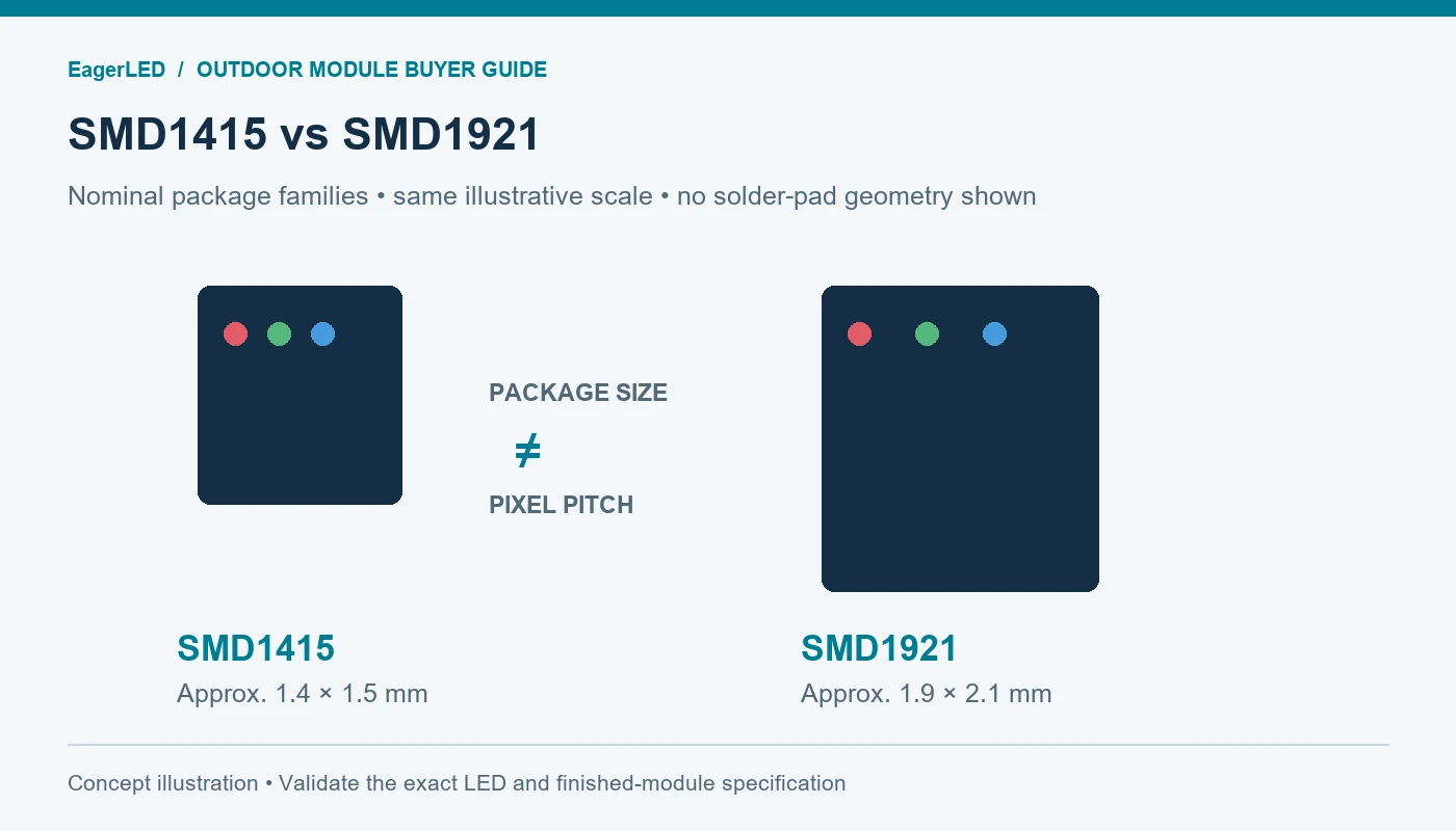
Two modules can share a pixel pitch and physical size while using different electrical designs. Check the original part number and revision, not just appearance. Use the site’s LED module information to identify product categories, then obtain explicit compatibility confirmation for the installed system.
| Item | What must be verified | Risk if overlooked |
|---|---|---|
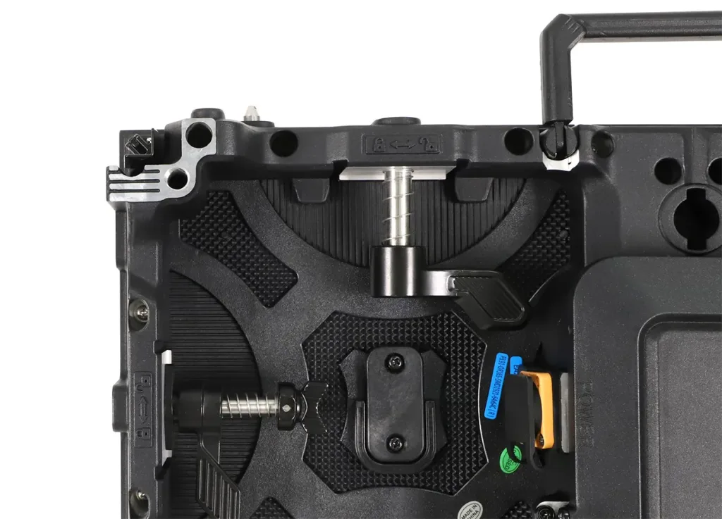
| Mechanical fit | Dimensions, mounting points, magnets or screws, service direction | Uneven surface, insecure mounting, damaged neighboring LEDs |
| Power requirements | Rated voltage, polarity, connector pinout, current demand | Damage, overheating, intermittent operation |
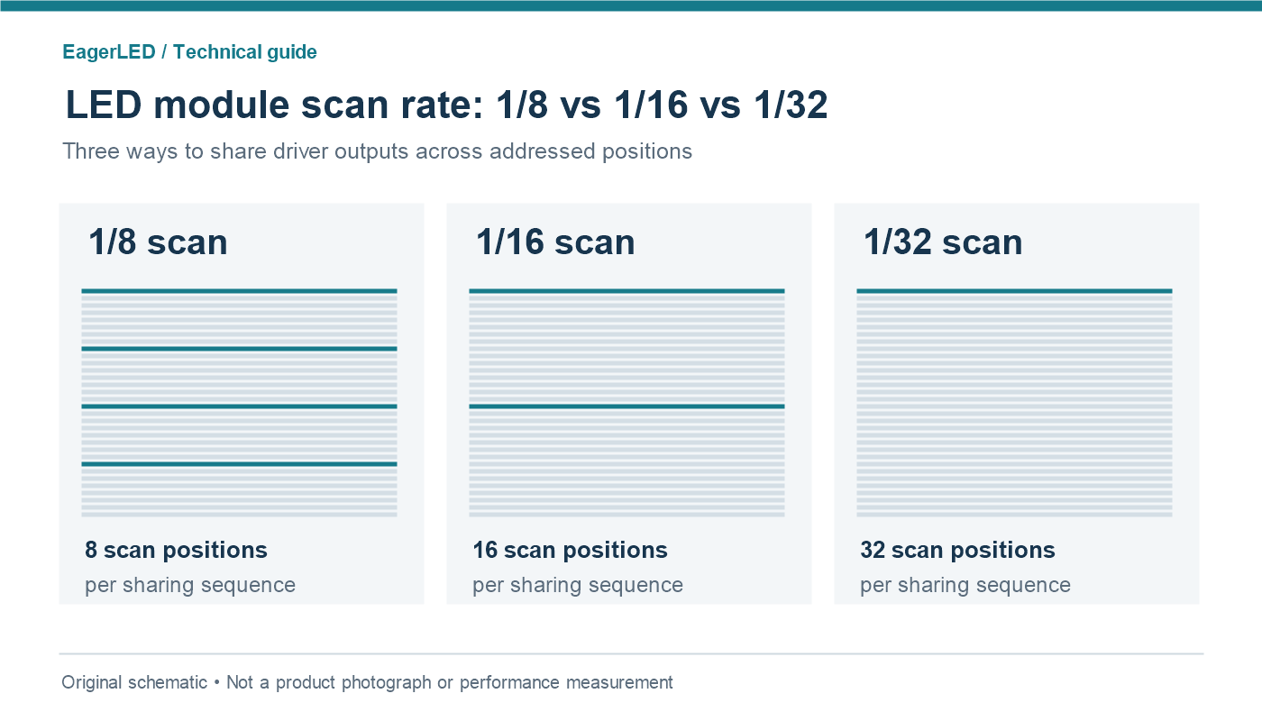
| Signal design | Interface, scan ratio, driver IC, pixel matrix, data order | Dark rows, scrambled image, wrong colors |
| Optical match | LED batch, mask, brightness, color characteristics, calibration | Visible patch or seam after replacement |
| Receiving electronics | Card model, HUB compatibility, firmware, approved configuration | Mapping errors or unsupported module operation |
| Environmental protection | Indoor/outdoor rating, gasket condition, coating, sealing method | Moisture or dust entering the serviced cabinet |
During LED screen repair, photograph cable positions before removal, label connectors, and protect the LED face. Use the approved front-service tool or rear-service procedure. Support the module so it cannot fall or strike adjacent pixels. Reinstall connectors without forcing them, restore strain relief and seals, and inspect alignment before power is restored.
03. Verify the repair before returning the screen to service
Run black, primary-color, white, low-gray, and grid patterns, followed by representative moving content. Check the repaired area and adjacent cabinets from the intended viewing distance. White reveals tint differences; low gray can expose uniformity problems hidden at high brightness; grid lines reveal mapping and alignment errors.
For LED screen repair acceptance, confirm stable operation after warm-up and after a normal restart. Use the manufacturer’s test duration and operating limits rather than inventing a universal burn-in period. Check that settings persist, alarms remain clear, and any redundant path works as designed. Save the final configuration and record the replaced component’s identity.
Daktronics documents lost receiving-card configuration as one cause of discolored modules on specified SLD systems. This is a useful reminder to distinguish configuration faults from failed LEDs; the documented procedure should not be applied indiscriminately to other products. For cabinet connections, see our LED receiving-card wiring checklist.
5. Safety precautions for LED screen repair
Safe LED screen repair begins with the manufacturer’s isolation procedure and the site’s electrical safety rules. Identify every supply, including backup feeds. Switching the image to black or shutting down the controller does not disconnect cabinet power. Qualified personnel must verify isolation using appropriate test equipment and allow stored energy to discharge as specified.
Keep operator checks separate from electrical work. Operators can record symptoms, inspect accessible external connections without opening energized equipment, and check approved software settings. Internal measurements on live equipment require appropriate qualifications, instruments, and controls. Do not use a non-contact indicator alone as proof that every relevant conductor is de-energized.
Use ESD controls when handling isolated electronic assemblies. An antistatic wrist strap protects components from static discharge; it is not protection against mains shock and must not be treated as such. Keep liquids, jewelry, loose screws, and conductive debris away from the work area. Use lifting and fall-protection arrangements appropriate to the installation.
Never defeat protective earth, bypass an interlock, or fit an oversized protective device to keep a display running. LED screen repair also includes mechanical safety: damaged cabinet locks, hanging points, or supporting structures require competent inspection. Restore covers and protective barriers before normal operation, and document unresolved defects instead of returning unsafe equipment to service.
6. LED display repair tools and preventive maintenance
Select LED display repair tools for the cabinet and task. More equipment does not compensate for missing service information. A labeled spare cable kit and a correct configuration backup can be more useful during an outage than an unverified replacement card. Keep compatible parts in protective packaging and track their revisions.
| Tool or resource | Useful purpose | Important limitation |
|---|---|---|
| Camera and cabinet map | Document symptoms and component locations | Camera banding may differ from visible flicker |
| Approved spare cables and modules | Controlled substitution | Confirm compatibility and safe supply before testing |
| Suitable multimeter | Qualified electrical checks | A steady reading does not exclude transient faults or ripple |
| Controller software and backups | Read status, mapping, configuration, calibration | Wrong files can affect previously working cabinets |
| Approved module removal tool | Release the correct front-service assembly | Unsuitable suction or magnetic force can damage surfaces |
| ESD workstation and rework equipment | Specialist bench repair | Requires training and a product-specific process |
| Approved cleaning materials | Remove dust without damaging components | Do not assume alcohol, detergent, or water is permitted |
Build preventive maintenance around the operating environment and manufacturer schedule. Before an event, inspect visible damage, accessible connections, and image uniformity. During scheduled shutdowns, trained staff should inspect cooling paths, seals, strain relief, and signs of overheating. Outdoor inspections should also account for storms and water ingress.
For cleaning, follow the exact surface and cabinet instructions. Exposed SMD LEDs, protective coatings, and encapsulated surfaces tolerate different methods. Do not spray liquid into the screen or assume a household cleaner is suitable. Record repeat faults by cabinet and component; recurring LED screen repair at the same position suggests an underlying connection, environmental, or loading problem.
7. LED screen repair FAQ
01. Can an LED display be repaired without replacing the whole wall?
Often, yes. Modular construction allows targeted LED screen repair using compatible modules, cables, power supplies, or receiving cards. First establish the fault location and check part availability. Extensive corrosion, structural damage, or widespread aging may make refurbishment or replacement a better option.
02. Why is my LED screen black when the power is on?
Possible causes include blanking, zero brightness, lost input, incorrect output mapping, or a downstream power or data fault. Check source and controller status, then use an internal pattern if supported. Power indicators alone do not prove that every module receives the correct supply and data.
03. How do I fix a flickering LED screen?
Identify whether the flicker is visible directly or only on camera. Compare source video with an internal pattern, then inspect the affected signal path and power system. LED screen repair should change one variable per test; replacing several components together makes the cause difficult to confirm.
04. Can I replace a module with another of the same pixel pitch?
Pixel pitch alone is insufficient. Match the approved part number, dimensions, voltage, pinout, scan method, driver design, mounting, and optical characteristics. A physically fitting module can still be electrically incompatible or show an obvious color difference after installation.
05. How much does LED screen repair cost?
The cost depends on the failed component, access, labor, shipping, calibration, and testing. Request an itemized quote tied to the cabinet model and observed fault. A flat price or promised savings percentage without diagnosis is not a dependable basis for budgeting.
06. Why does a replacement module look brighter or a different color?
Possible reasons include a different LED batch, aging of neighboring modules, incompatible settings, or missing calibration data. Check hardware compatibility first, then use the approved calibration workflow. Do not compensate by arbitrarily changing power-supply voltage.
07. Is it safe to power on a screen after it gets wet?
Do not restore power simply because the visible surface looks dry. Isolate the affected equipment and arrange qualified inspection of moisture, corrosion, insulation, and the ingress path. LED screen repair after water exposure must establish safe operation before testing normal content.
8. Conclusion: diagnose, repair, and verify
Effective LED screen repair follows a repeatable sequence: document the symptom, identify its boundary, separate source problems from display faults, test one variable at a time, and fit approved replacement parts. Finish with pattern checks, realistic content, restart verification, and a saved service record.
Use this LED display repair guide alongside the exact cabinet and controller manuals. When the fault exceeds safe operator checks, provide the manufacturer with evidence and request a targeted diagnosis. Careful LED screen repair restores the picture while addressing the reason it failed, helping prevent the same interruption from returning.
 Korean Customers Visited EagerLED LED Wall Screen Factory
 EagerLED LED Screen Modules In America